
Porphyry model
In this tutorial, we explore modelling a porphyry deposit, characterized by a central intrusive stock surrounded by concentric zones of hydrothermal alteration. The porphyry model requires multiple non-conformal groups and careful assignment of overturned orientations to ensure the intrusion and its alteration halos are modelled correctly.
To access the data used in this tutorial, download the “porphyry_model.geoh5” here
Note
This tutorial is based on a synthesis of a few porphyry deposit cross-sections [HaDT15], [HoCD07], [LoGu70].
Setup
The porphyry model is built from a central intrusive stock extending from a larger intrusion.
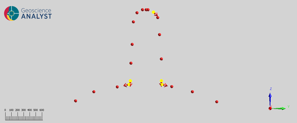
Fig. 71 Contact points and orientations for the intrusion and upper stock. Overturned orientations are highlighted yellow.
Porphyry deposits are associated with several zones of alteration. The potassic alteration zone overlaps with the stock. We modelled a zone of core potassic alteration in the upper margins of the stock where ore tends to concentrate.
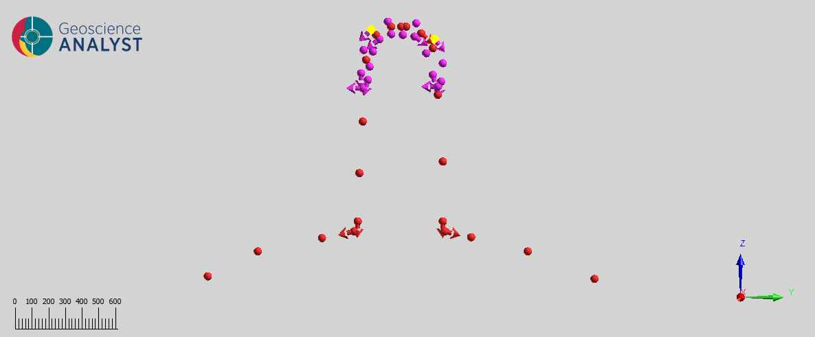
Fig. 72 Contact points and orientations for a cap of ore in the upper extent of the potassic alteration zone. Overturned orientations are highlighted yellow.
On the flanks of the larger intrusion is a zone of sodic-calcic alteration.
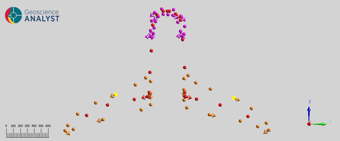
Fig. 73 Contact points and orientations for the sodic-calcic alteration zone. Overturned orientations are highlighted yellow.
Surrounding the potassic alteration of the stock is a concentric zone of phyllic (sericitic) alteration.
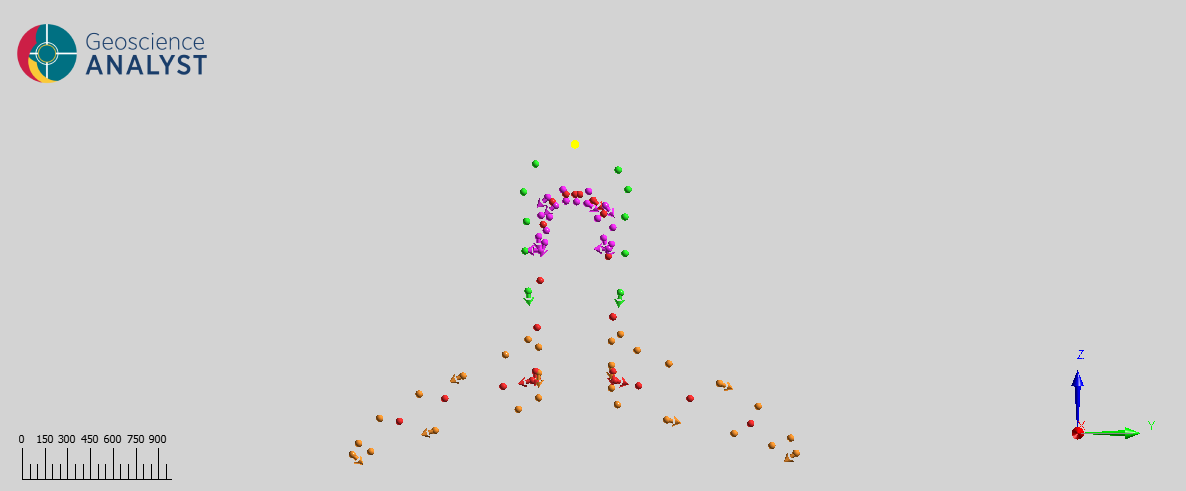
Fig. 74 Contact points and orientations for the phyllic alteration zone. Overturned orientations are highlighted yellow.
An outer shell of propylitic alteration encloses the entire upper portion of the porphyry system.
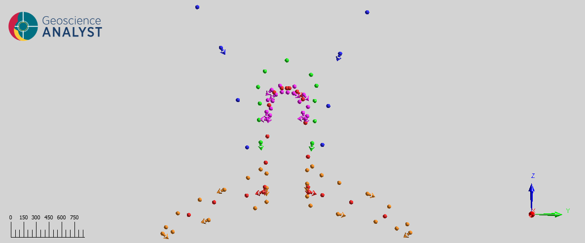
Fig. 75 Contact points and orientations for the propylitic halo
Above the stock and extending to the surface is a zone of argillic alteration.
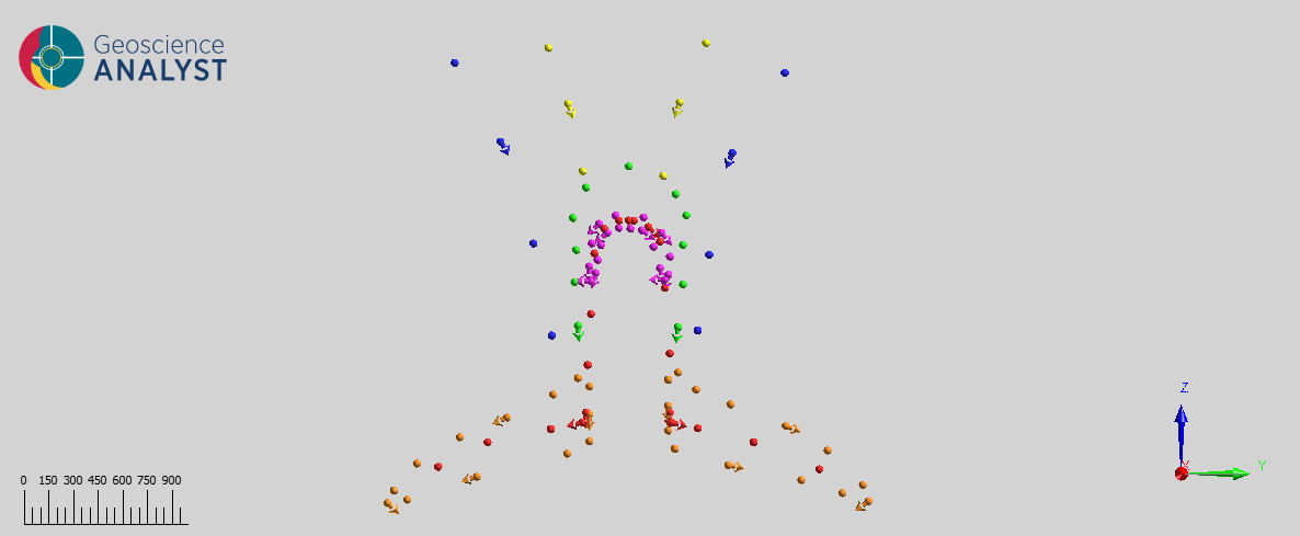
Fig. 76 Contact points and orientations for the argillic alteration zone.
The porphyry model is assembled in the UI as a stack of non-conformal groups. The order of the units is important to ensure that the overprinting of adjacent zones is correct. For example, the argillic zone must be younger than the phyllic and propylitic zones to overprint the central region. The figure below shows the history used to model the porphyry deposit with older units at the bottom.
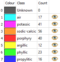
Fig. 77 History table showing the age relations for units from older (bottom) to younger (top).
Modelling the porphyry deposit
To run GemPy on our synthesized porphyry observations, fill out the UI with the appropriate object/data selections.
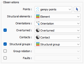
Fig. 78 GemPy dialogue for the observations section.
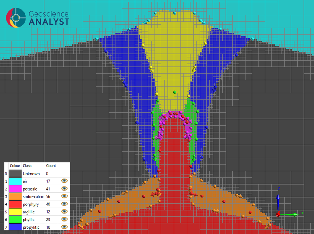
The resulting model correctly captures the intrusion and the concentric zones of alteration. The age relationships are respected and the overturned orientations are correctly applied to the intrusion and alteration zones.
Fig. 79 GemPy modelling results for a porphyry deposit including a central stock and its associated zones of alteration.
References
Halley, S; Dilles, J.H.; Tosdal, R.M.: Footprints: Hydrothermal alteration and geochemical dispersion around porphyry copper deposits. SEG Newsletter 100 (2015).
Holliday, J.R.; Cooke, D.R.; Dilles, J.H.: Advances in geological models and exploration methods for copper +/- gold porphyry deposits. Proceedings of Exploration 07: Fifth Decennial International Conference on Mineral Exploration 791-809 (2007).
Lowell, J.D.; Guilbert, J.M.: Lateral and vertical alteration-mineralization zoning in porphyry ore deposits. Economic Geology 65 373-408 (1970).